Essential Rules for Floor Layout: Layering and Functions secrets
How to set Floor Layers Properly in Revit?!
One of the most important elements in Revit is the Floor tool, which significantly impacts the accuracy and quality of your design and schedules. In this guide, we'll explore the world of floors in Revit, focusing on layering rules and functions to help elevate your Revit expertise.
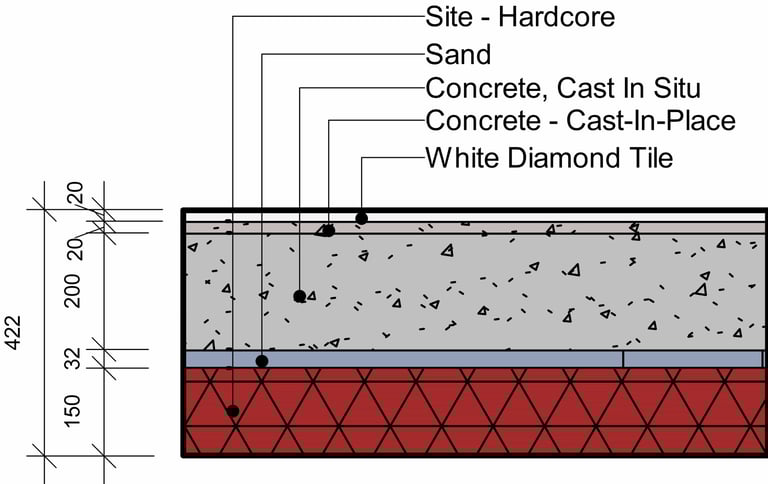
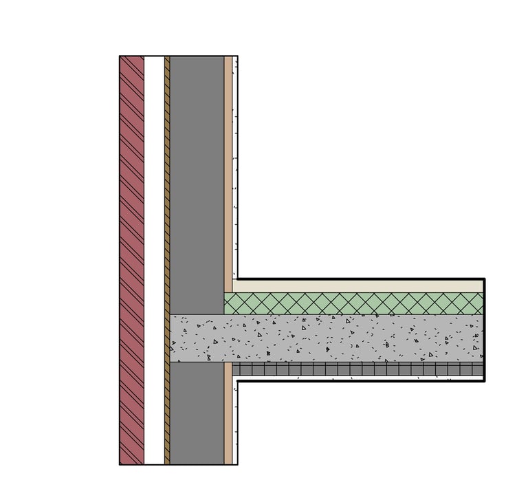
If you examine any section of a floor, you will find multiple layers made of different materials. Each of these layers has a specific thickness and unique functionality. For instance, there may be a substrate layer made of cement with a thickness of 2 cm, structured to support the flooring material.
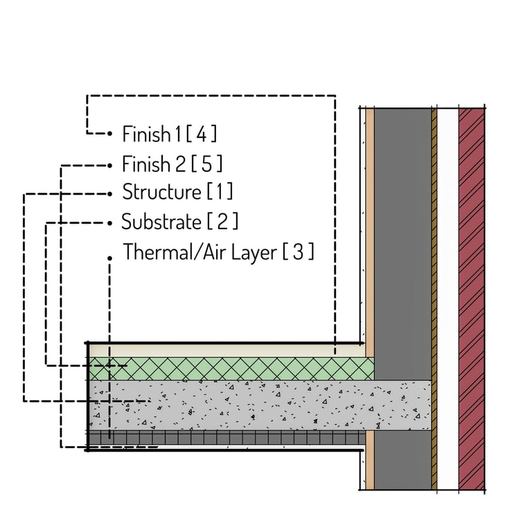
There are six functions in Revit for floor layers. We need to understand what they are and where they are used to determine how they should be layered.
Structure [1]
This is a must-have layer in any type of floor or wall. Any floor should have at least one structural layer in its core boundary. It can be assigned a variety of materials and thicknesses.
Substrate [2]
Substrates are the layers on which floor covering materials are applied. They can be made of wood, concrete, plywood, stone, or metal. Proper preparation of these surfaces is essential to ensure a successful flooring installation, regardless of the material used.
Thermal/Air Layer [3]
This layer refers to a specific layer used within floor, wall, or roof assemblies to represent the thermal resistance and air barrier properties of building elements. Membrane Layer A waterproofing membrane is a layer of watertight material that lies on a surface to prevent water leaks or damage. The membrane layer should have zero thickness.
Finish 1 [4]
This layer is typically the outermost layer on the exterior side of walls or the top layer of a floor. It may also be considered the layer just before the last layer because of its priority number.
Finish 2 [5]
The Finish 2 layer is usually used as the last interior layer for walls or the final layer in floors.
Now that we understand the functionality of these layers, we also need to know about their priority and adjustment. If you pay attention to the numbers next to each layer, you will see how they should be ordered.
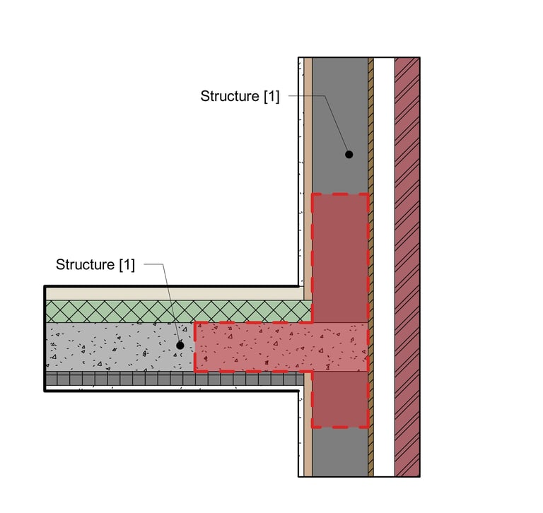
The structure layer, which has the highest priority (number 1), is the layer that, when set correctly while joining a wall, cuts through all layers of that wall with lower priorities until it reaches either the core boundary or another structure layer with the same priority number.
Conversely, the Finish 2 has the lowest priority (number 5). In between, we have the substrate layer with the second highest priority (number 2), followed by the thermal/air layer (priority number 3), and finally Finish 1, which has a priority of 4.
Based on the information we reviewed, now let's check the rules that come from them with some examples:
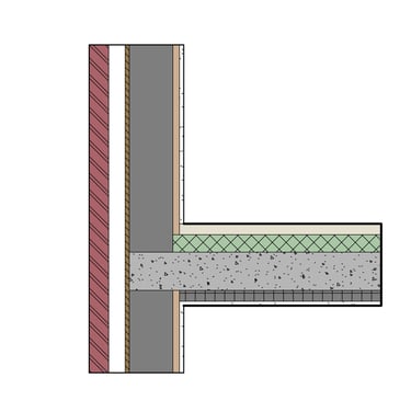
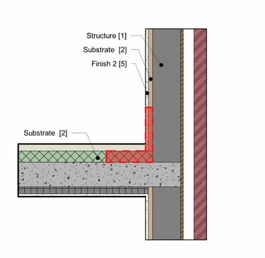
1. Since Revit first connects and joins the layers with the highest priority, we can see that the structural layer of the floor cuts through all of the layers with lower priority on the interior side and continues until it reaches the core boundary.
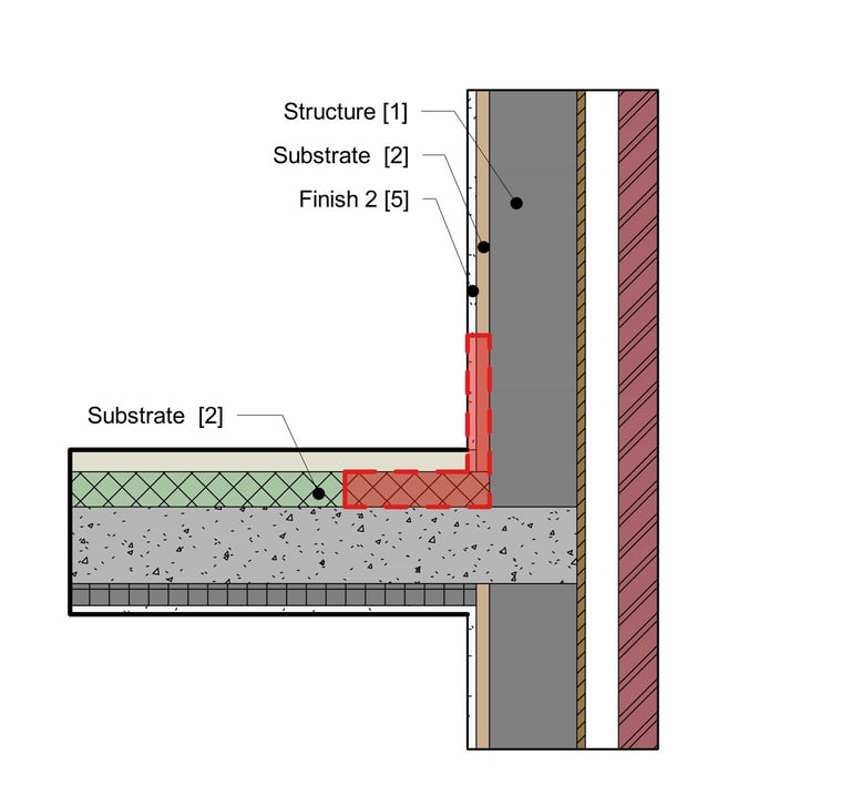
2. The substrate layer with a priority level of 2 cuts through Finish 2, which has a lower priority of 5, as well as another substrate layer with the same priority level. However, because its priority level is lower than that of the structural layer, it was unable to cut through the wall structure.

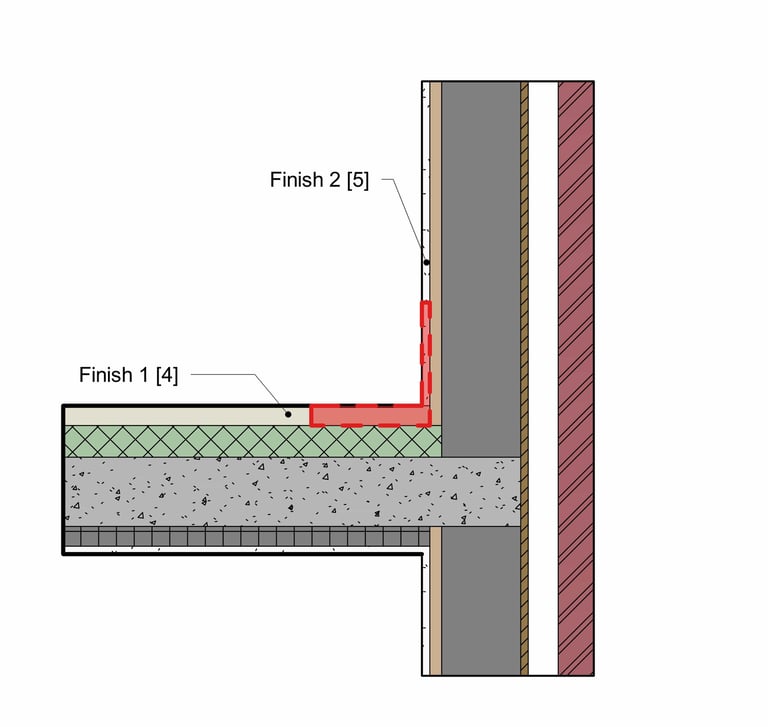
3. The last layer of the floor is Finish 1, and it cuts the interior layer of the wall, which is Finish 2, because it has a higher priority. If the priority of the two layers were the same but they had different materials, a line would appear at the join.
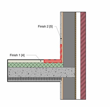
4. The final layer of the floor and the interior layer of the wall have the same priority as Finish 2 [5], and they are made of the same materials. When these layers join, the connection is simplified if both layers consist of the same material.

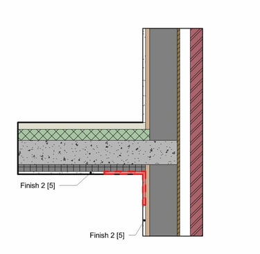
5. As the last rule, it is noteworthy that all layers within the core boundary, regardless of their priority, pass through layers of higher priority that are located outside the core boundry. The layers in the core extend to the core of a joined wall, even if those core layers are set to Priority 5.
For example, if the core of a floor contains a Thermal/Air layer [3] and a Finish 2 layer [5], these layers can pass through the Structure [1] and Substrate [2] layers if they are positioned outside of the core boundary.
If you're excited to learn more about floors and take your skills to the next level, don't miss our informative video below! It’s packed with insights that will inspire your creativity.

Your essential resource for Revit and BIM expertise. Find our comprehensive courses, professional families, and expert blog to elevate your skills.
© 2025 RVT PLUS. All rights reserved.
Quick Access
Recent Articles
Explore Our Shop